Changeover Switch Fan Coil Wiring Diagram

Automatic Changeover Switch For Generator Circuit Diagram In 2019

Gentran Power Stay Indoor Manual Transfer Switch Wiring Diagram

Best Of Wiring Diagram Peugeot 307 Radio Diagrams Digramssample

12v Changeover Relay Wiring Diagram With Images Light Switch

Wiring Diagram Standby Generator Baldor

Wiring Diagram For Generator Transfer Switch Diagram

This solution allows existing line voltage wiring between the fan coil unit and temperature controller to be re used.
Changeover switch fan coil wiring diagram. Se7000 fan coil unit application guide. All field installed conductors should have an insulation rating of 300 volts or greater. A changeover switch switches a house s electricity supply from the general grid power supply to a generator system in case of power outage. Units are horizon tal concealed and are available with an exposed fan plenum or ceiling access panel.
Circuits 4 pipe coil connections. Dec 10 2017. Thanks go to bob wilson volvodad on brickboard for contributing to these differences. Your auto changeover switch will also feature 4 pole contactors with a 230v coil voltage and a phase monitoring relay.
Manual changeover switch wiring diagram for portable generator. 752 1 the mars series 390 change over switches are used for summer winter change over of electric thermostats in hydronic heating cooling fan coil units. In a changeover relay the 87a pin will be hot anytime the 87 pin is off so long as power is connected to pin 30. The changeover switch connects to the main power grid generator or alternate source and the house wiring.
2 pipe fan coil unit with 3 speed fan and wirelesss window switch. Dec 10 2017 two way light switch diagram or staircase lighting wiring diagram. The basic series fan coil design is for the market that requires only the basic features of our standard unitrane fan coil. 2 pipe chilled water hot water changeover fan coil system cdxx139 mechanical 25 oct 13 13 57 if you dont end up scrapping the changeover syste 4 pipe is way more money the size your pipe and flow for cooling then back engineer the heating coil with the same gpm.
Buy an electrical changeover switch from expert electrical. The incoming connection is found at the bottom of the unit and the outgoing load at the top. Suggested electric fan wiring diagrams page 1. Electric fan fan coil unit ceiling fan motor stand fan hunter ceiling fans pedestal fan diagram design motors.
This type of relay will work for this application also but you will not use pin 87a. Field power wiring marked terminal plug and receptacle label 3 9 11 7 3 2 yel orn vio relay 1 22 vdc coil rec field power wiring see rating plate disconnect per nec for volts hertz gnd l1 l1 l2 or. Fan coil wiring diagram typical with unit mounted three speed fan switch note. Schematic diagram single supply circuit component arrangement legend cb fu gnd htr.
L6076a replaces white rodgers. Page 27 wiring diagrams figure 36. Ship loose accessories include a remote mounted fan speed switch.

Wiring Diagram For Multiple Lights One Switch Valid 4 Incredible
Double Throw Switch Wiring Diagram

Best Relay Wiring Diagram 5 Pin Bosch Endearing Enchanting

Wiring Diagram Of Washing Machine Generator Transfer Switch Diagram

New Wiring Diagram For Ac Blower Motor Diagram Motor Capacitors

Manual Changeover Switch Wiring Diagram For Portable Generator

Image Result For 3 Phase Changeover Switch Circuit Transfer
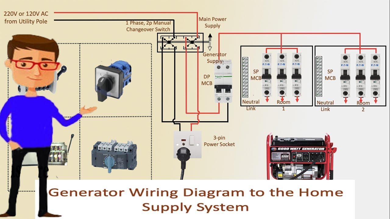
Generator Wiring Diagram To The Home Supply System Generator
